Electrical 3D
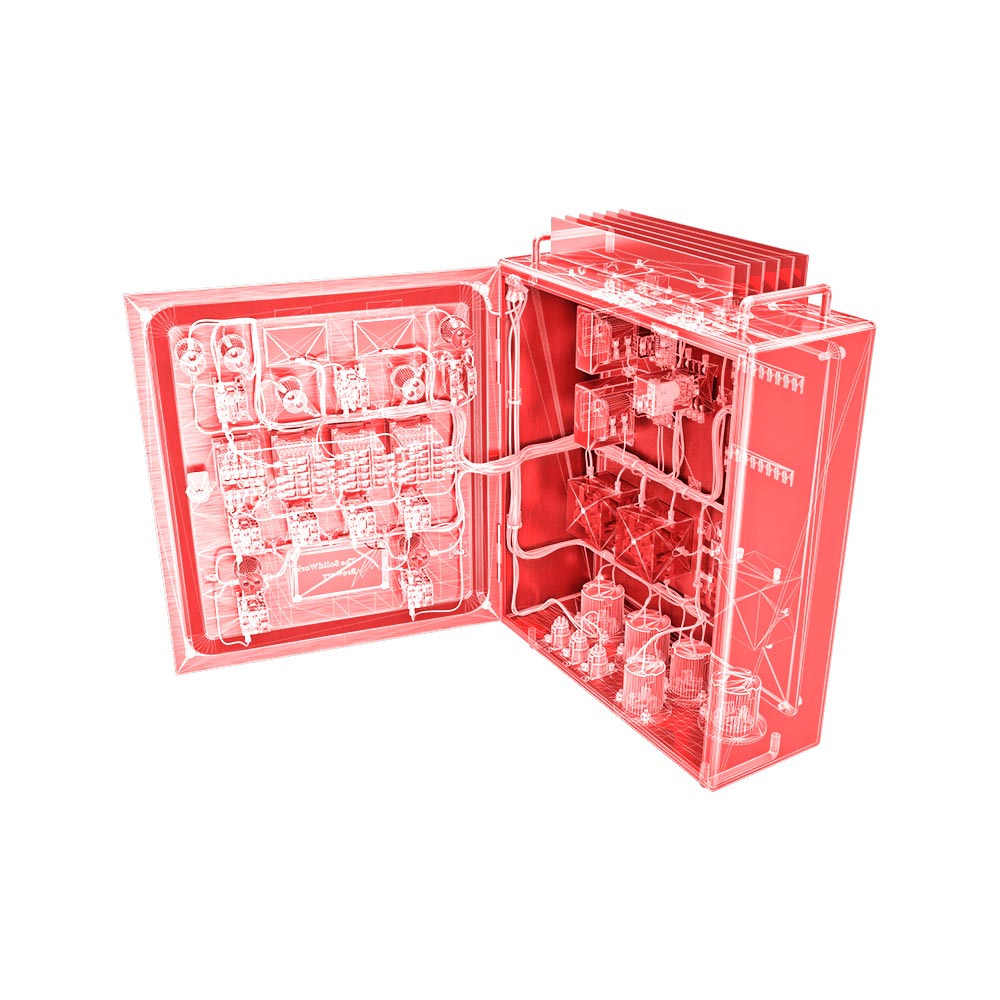
SOLIDWORKS Electrical 3D enables you to place electrical components and use SOLIDWORKS routing technology to automatically interconnect electrical design elements within a 3D model. 2D schematics and 3D models are synchronized so any changes are automatically updated.
SOLIDWORKS® Electrical 3D enables you to easily integrate your electrical schematic designs into your SOLIDWORKS 3D product model.
SOLIDWORKS Electrical 3D enables you to place electrical components and use SOLIDWORKS routing technology to automatically interconnect electrical design elements within a 3D model. 2D schematics and 3D models are synchronized so any changes are automatically updated.
Collaborative Electrical-Mechanical Development
SOLIDWORKS Electrical 3D meets the needs of multi-user and cross-disciplinary projects with a coordinated design process between electrical and mechanical teams to execute electrical systems in a SOLIDWORKS 3D CAD model readily. SOLIDWORKS Electrical 3D’s advanced database technology allows for bi-directional data in a multi-user environment. These means multiple electrical and mechanical engineers can work on the same project simultaneously in real time.
Real-Time Synchronization
SOLIDWORKS Electrical synchronizes data from project design in real time, bidirectionally in a shared multi-user environment between 2D schematics and the 3D model. This synchronization unifies key information between consumers and design disciplines.
Electrical Design In 3D CAD
Designers and engineers will incorporate SOLIDWORKS Electrical 3D electrical schematic design data into a SOLIDWORKS 3D CAD model for CAD-embedded, electrical system design. This real-time, bi-directional, multi-user method facilitates more collaborative design between electrical and mechanical designers, and allows electrical components to be positioned or removed in the 3D CAD model. Easily create the electrical interconnection of the electrical 3D elements with auto-routing that allows the planning and recording of route paths and related data (such as the length of wires, cables, and harnesses within the system).
Auto-Routing
Advanced SOLIDWORKS routing technology to simplify the wire, cables, and harness auto-routing process within the 3D CAD model.
Electrical Component Library
Through an easy-to-use import wizard, a comprehensive integrated library of manufacturer parts offers an easily customizable and adaptable parts base.
Streamlined
SOLIDWORKS-inspired intuitive and easy-to-use interface with a clear editor and implementation model between schematic capture and layout of the document.
Embedded Electrical System Design Planning
SOLIDWORKS Electrical 3D is an easy-to-use planning tool for the rapid collaborative design of schematically specified embedded electrical systems that can be implemented with an intuitive graphical user interface and the knowledge of conventional multi-line software in a SOLIDWORKS 3D CAD model. SOLIDWORKS Electrical 3D creates a new technology framework, integrating purpose-built design tools for the creation of embedded electrical subsystems with schematic drives.
3D Electrical Cabinet Design
SOLIDWORKS Electrical 3D incorporates SOLIDWORKS CAD and Electrical technology to provide an improved design experience for the construction of electrical 3D cabinets. This unified system is coordinated without the use of external files in real time, and can use existing CAD designs. SOLIDWORKS Electrical 3D provides robust electrical 3D cabinet modeling and documentation capabilities with the SOLIDWORKS automation software.
Electrical Harness Design Planning
SOLIDWORKS Electrical 3D offers a virtual “design-in-place” electrical system development environment that provides auto-routing of a schematically specified electrical harness in a SOLIDWORKS 3D CAD model, simplifying the production of harnesses while minimizing errors. Once the virtual harness is developed, SOLIDWORKS Electrical 3D can use the built-in drawing tools to generate detailed assembly drawings. Such drawing development resources include the ability to create ballooned assemblies, pin boards or cut list sketches, as well as related documentation on the BOM.

